Fundamentals of Seven segment displays
Introduction to Seven segment displays
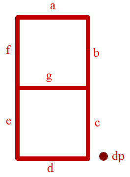
Character display that is commonly used these days are called seven segment displays because they are easy to read under low ambient light. Another type of display is called LCD display which are useful in low power or battery operated system.
Unlike LEDs, LCDs are visible in bright ambient light. Since LCDs do not emit light, they are visible in low light environment. These days, a combination of LCDs and LEDs are used to enable LCDs to be visible even in low ambient light environment. LCDs are not efficient at low temperature environment. The characters size available are in 0.3 inch, 0.6 inch and larger sizes.
Seven Segment Schematic
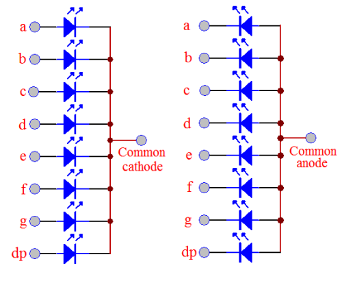
Seven segment display can be divided into 2 types of connection. One is called common anode of which all the anodes of the LEDs are connected together, leaving the cathodes open for connection.
The other one is called common cathode of which all the cathodes of the LEDs are connected together, leaving the anodes open for connection.
The figures below show a simplified display where there are 8 LEDs on one display. Each of the LED can be turn on or off by controlling the signals to each LED.


Applications and Drivers
A numeral to be displayed on a seven segment display is usually encoded in BCD form, and a logic circuit driver ON or OFF the proper segments of the display.
This logic is also called decoder. Various decoders are available to drive common anode and common cathode displays. One of the easily available decoder is 7447 AND 7448 TTL decoders. They are open collector TTL that are designed to pull down common anode (7447 type) and common cathode (7448 type) through external current limiting resistors.
In order to reduce the energy consumption, the pulsing of the display voltage is implemented. This technique is called multiplexing that allows a single decoder to be shared by several digits. The digits are connected together in parallel i.e. all the "a" are connected together and so on.
The multiplexer logic sends input data for a digit into the encoder and enables the common element of the correct digit. This process is repeated for each digit. The segment is energized only when both a segment and its associated common lead are selected. With this system, only one digit is energized at any instant, a factor that reduces the power supply requirements of the system.
When using multiplexing, ensure that the peak and average current specifications of the display is adhered to.
Back To Seven Segment Displays Home Page


New! Comments
Have your say about what you just read! Leave us a comment in the box below.