Garden Watering Circuit Project
This Garden Watering Circuit Project uses an OP-AMP with hysteresis that will automatically ON the water valve of your garden device to water the plants if the moisture detected of the soil is lowered than your desired level. You will need to do a bit of experiment in order to get the best results.
Two home made probes that are made from stainless steel rods and are set to be about 1 inch apart are used to detect the moisture of the soil. Each rod can be of length of about half a feet and a diameter of 1/16 of an inch. Other dimensions will also do.
The power used in the circuit is 12V DC but a 9V DC will also do provided you can find a DC relay that can be powered up using a 9V power supply. In this circuit, the op-amp will have an output at pin 3 of HIGH or LOW depending on the voltage levels of input pins 2 and 3. If pin 2 voltage level is higher than pin 3, the output will be low and vice versa.
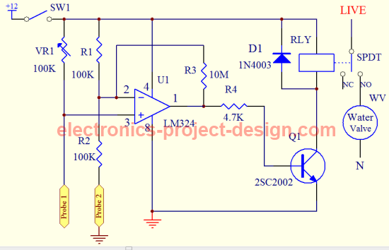
Garden watering circuit schematic. Fine tune this circuit if necessary for best results
Probe 2 is connected to the ground of the circuit. Resistors R1 and R2 act as voltage divider that will divide the input voltage at pin 2 to 6V DC. When the probes 1 & 2 are placed a few inches into the ground, there will be resistance between probe 1 and probe 2. VR1 is used to adjust the moisture level needed.
For example, set VR1 to 100K. When the soil is dry, the resistance between probe 1 and probe 2 will be higher than 100K causing voltage at pin 3 to be higher than pin 2. This will cause the output U1 to be HIGH. When this happens, the transistor Q1 will turn ON. This will cause the 12V DC relay to also turn ON. The water valve will activate and the plants will be watered.
A SPST relay can also be used as the NC connection is not used in this case.
When the soil around probes 1 and 2 began to moist due to the opening of the water valve, the resistance will drop until voltage at pin 3 drops below pin 2. When this happens, the output of U1 will turn OFF which in turn will turn OFF the RLY. When this occurred, the water valve will be turned OFF.
You will need to decide where to place the probes in determining the area that you want to water. Experiment the moisture level by adjusting potentiomenter VR1 until you are satisfied with it.
Garden Watering Circuit Parts List
| Label | Description |
| R1 | 100K ohm 1% 1/4W Metal Film Resistor |
| R2 | 100K ohm 1% 1/4W Metal Film Resistor |
| R3 | 10M ohm 1% 1/4W Metal Film Resistor |
| R4 | 4.7K ohm 1% 1/4W Metal Film Resistor |
| VR1 | 100K ohm Potentiometer |
| SW1 | SPST switch |
| Q1 | 2SC2002 NPN Transistor |
| RLY | 12V SPDT DC Relay |
| U1 IC | LM324 |
| D1 | Diode 1N4003 |
| WV | Water Valve |
| Probe 1, Probe 2 | Stainless steel rods |
Back to Garden Watering Circuit Home Page

Recent Articles
-
Electronics Events
Join the electronics events to enhance your knowledge and network with other professionals in this industry. -
Electronics Design Contest
 Join electronics design contest and win prizes. Test your hardware and software skills against the best designers from the rest of the world.
 -
Garden Watering Circuit
 Experiment and test out this automatic garden watering circuit that will detect the moisture of the soil and on or off the water valve accordingly.
Design and build a battery tester to test dry cell and rechargeable battery with a voltage of less than 2V. Check here.
PCB Prototypes
Make your own printed circuit board and learn the processes involved along the way. More here.
Learn how to dissipate heat from your heat-sensitive electronic components.
Test the reliability of your products to the environment by stressing them in test lab.
Explore the use of 7-Segment Display, 555 Timer, Decade Counter and Binary Adder. Get the circuit.
Construct this simple door bell chime and have fun. Find out more here.
Build this simple home alarm to protect your house from intruders. See the schematic circuit.
New! Comments
Have your say about what you just read! Leave us a comment in the box below.