Electronic Kitchen Timer Circuit
Kitchen Timer Circuit Project
Ever wonder how an electronic kitchen timer circuit works? This project can be used to design a timer that will on a buzzer from 1-10 minutes or 10-100 minutes by changing the values of the timer capacitor.
It uses a 555 timer integrated circuit configured as an astable mode with frequency that can be changed by changing the values of VR1 and capacitor C1. The circuit uses a 12V DC power supply with the capacitor value of 0.1uF for a timer duration of less than 10 minutes. If longer timer of up to 100 minutes is required, use a 1uF electrolytic capacitor for C1.
The frequency generated by the timer is given by the equation below. This clock pulses generated are then fed into the CLK input of the binary counter.
Frequency = 1.44/{[R2+2(VR1+R1)]C1}
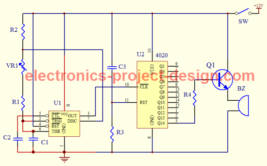
4020B 14-Stage Binary Counter
This binary counter will count the number of input pulses and generate the output Q14, Q13 ..... Q5, Q4, Q1 accordingly. A negative edge pulse signal from the output pin 3 of 555 timer to the Clock input of 4020B Binary counter will increment the sequence. When the RESET pin of 4020B is applied with a HIGH input, the counter will be reset to zero.
The outputs from Q14.... Q1 can have a binary values from zero to 3FFF(Hex) or 16,383(decimal). For example, if the clock input has a square wave frequency of 1 Hertz, than every 1 second will increase the counter by 1. If the frequency is set to 10 Hz, every 0.1 second will increase the counter value by 1.
In this circuit, only Q14 is used to activate the buzzer. Hence, 8192 pulses would have passed before it turns on the transistor Q1 which will turn on the buzzer. For example, if the CLK frequency is 10 Hertz (period T=0.1sec), the buzzer will sound 8192 X 0.1 seconds later. 819.2 seconds is about 13 minutes. By adjusting the values of VR1, you will be able to adjust the timer between 1-10 minutes.
If you require a longer delay, change the capacitor C1 from 0.1uF/25V to an electrolytic capacitor of 1uF/25V. This change will help to increase the timing as the frequency is now 10 times lower than the previous circuit. A 1 Hertz frequency means the duration of the pulses is now longer i.e. the period T= 1 second. Hence by adjusting the value of VR1, you will be able to change the timer to between 10-100 minutes.
Parts List
| Label | Description |
| R1 | 39K ohm 5% 1/4W Carbon Film Resistor |
| R2 | 4.7K ohm 5% 1/4W Carbon Film Resistor |
| R3 | 1M ohm 5% 1/4W Carbon Film Resistor |
| R4 | 4.7K ohm 5% 1/4W Carbon Film Resistor |
| VR1 | 470K ohm Potentiometer |
| SW | Single pole single throw switch |
| C1 | 0.1uF/25V Ceramic Capacitor |
| C2 | 0.01uF/25V Ceramic Capacitor |
| C3 | 0.1uF/25V Ceramic Capacitor |
| Q1 | PNP 2SC2002 Transistor |
| U1 | 555 Timer IC |
| U2 | 4020B Binary Counter |
| BZ | Buzzer 12V DC |
Back to Kitchen Timer Circuit Home Page

Recent Articles
-
Electronics Events
Join the electronics events to enhance your knowledge and network with other professionals in this industry. -
Electronics Design Contest
 Join electronics design contest and win prizes. Test your hardware and software skills against the best designers from the rest of the world.
 -
Garden Watering Circuit
 Experiment and test out this automatic garden watering circuit that will detect the moisture of the soil and on or off the water valve accordingly.
Design and build a battery tester to test dry cell and rechargeable battery with a voltage of less than 2V. Check here.
PCB Prototypes
Make your own printed circuit board and learn the processes involved along the way. More here.
Learn how to dissipate heat from your heat-sensitive electronic components.
Test the reliability of your products to the environment by stressing them in test lab.
Explore the use of 7-Segment Display, 555 Timer, Decade Counter and Binary Adder. Get the circuit.
Construct this simple door bell chime and have fun. Find out more here.
Build this simple home alarm to protect your house from intruders. See the schematic circuit.
New! Comments
Have your say about what you just read! Leave us a comment in the box below.