Variable DC Power Supply Using LM317
Variable DC Power Supply
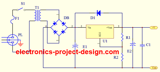
Variable DC power supply is one of the projects that every electronics student should build. Building your own power supply is fun and using it throughout your constructional projects is the reward of your achievement. This project uses a transformer to step down the incoming AC voltage to 12.5V AC.
This circuit is designed for incoming voltage of 240VAC. If 110VAC is required, a 110/12.5 power transformer should be used. The step down AC voltage is then rectified by using a diode bridge. The rectified DC voltage is smoothened using a 2,200uF/50V electrolytic capacitor.
The rectified voltage is then fed into the input of an adjustable voltage regulator LM317. This three terminal voltage regulator has an output voltage operating range from 1.2V to 37V DC with a maximum load current of up to 1.5A. One of the manufacturers of this device is Fairchild Semiconductor.
This regulator has an internal short circuit current limiting protection i.e. if you short the output of the regulator, it will automatically shuts down. Once the short circuit has been removed, it will go back to its normal operating mode. The internal thermal overload protection will also ensure that it shuts down when the operating temperature becomes too hot.

The output voltage is controlled by resistors R1 and R2. The recommended value of R1 is in the region of 240 ohm and the value of R2 used is determined by the output voltage required. The output voltage is given by the following equation.
IAdj is the adjustment current with a value of about 45uA. As the current value is small, it is negligible hence the formula used for calculation is:
Vo = 1.25(1+R2/R1)
R2 = R1(Vo/1.25 - 1)
If the supply is designed to output a 12V DC, use a R2 = 2200 ohm. A heatsink should also be used to ensure that the heat generated in LM317 can be dissipated to the environment. Fuse F1 is used to ensure that if overcurrent happens, it will disconnect the primary circuit from the mains supply. Capacitor C1 is used to bypass the high frequencies content due to transients or other electrical noise.
An additional diode D1 is used to protect the LM317 in case the secondary voltage is higher than the primary during power down of the circuit. Make sure that you use power wires that is thick enough to handle the current. A suggested gauge of at least AWG #20 for wire leads should be used. You will also need to have casing to house the printed circuit board. There are many standard casings that you can purchase from any electronic shops.
Variable DC Power Supply Parts List
| Label | Description |
| R1 | 240 ohm 5% 1/4W Carbon Film Resistor |
| R2 | 2.2K ohm 5% 1/4W Carbon Film Resistor |
| S1 | Switch 250VAC/2A |
| C1 | 0.1uF/50V Ceramic Capacitor |
| E1 | 2,200uF/50V Electrolytic Capacitor |
| E2 | 100uF/50V Electrolytic Capacitor |
| DB | 2A/50PIV Diode Bridge |
| D1 | 1N4003 Diode |
| U1 | LM317 Adjustable Regulator |
| F1 | Fast Acting Fuse 250VAC 500mA |
| T1 | 240/12.5 25VA Power Transformer |
| PL | AC Power Plug with cord. |
Back To Variable DC Power Supply Home Page


New! Comments
Have your say about what you just read! Leave us a comment in the box below.