Room Thermostat
Room thermostat which is used to control heating or cooling system in air conditioning and heating system has been one of the common device used in residential and industrial buildings to control the temperature of a space in a warehouse, a room, a hall or an office.
This room thermostat project will focus on the chilled water control of a space that uses chilled water as its source of cooling. The controller basically consists of a comparator that controls the ON and OFF of the chilled water valve based on the sensor temperature.
The control of the fan speed is usually hardwired with two speed or three speed motors and is incorporated into the thermostat. The temperature range of this thermostat is from 5 °C to 30 °C with a tolerance of approximately 3 °C. Hence, only non critical tolerance control of temperature control such as a room can be used.
Circuit Description
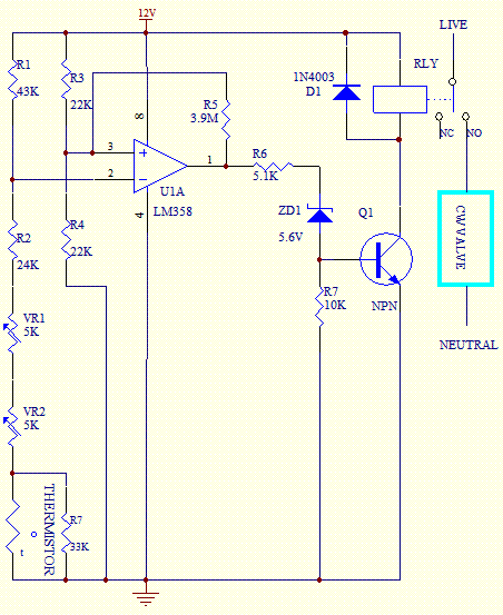
The circuit diagram shows the configuration of the Room Thermostat. The LM358 Op Amp is used as a comparator to sense theinputs of the reference voltage (PIN 3) and room temperature (PIN 2). The thermistor used is a NTC (negative temperature coefficient) type where its resistance will drop when the temperature increases and vice versa. It has a resistance of of 20K ohm at 25 °C.
When the room temperature increases, the thermistor resistance will drop and hence the output of the operational amplifier will be high. This cause transistor Q1 to turn ON and the relay is turn ON. The COM position of the relay contact will switch to NO and ON the chilled water valve which allow the cold water to pass through the coil.
The cold air from the coil is transferred to the room by the fan until the temperature of the room goes down to its set point again.

The hysteresis of approximately 2 °C is achieved with the positive feedback resistor R5. This feedback is used to prevent the chattering of the relay when the temperature sensing has yet to stabilize. The circuit is calibrated using variable resistor VR1. Set the lever of the slide potentiometer or rotary potentiometer VR2 to 25 Celcius location.
Place the thermistor at a space where the temperature is at 25 Celcius. By varying VR1, set the resistance at the position between the ON and OFF of the relay. Use a suitable contact relay rating according to the load of the water valve.
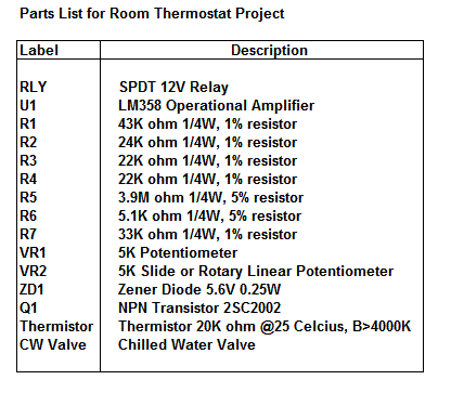
Parts List


New! Comments
Have your say about what you just read! Leave us a comment in the box below.