Microcontroller Based Project LED Driver
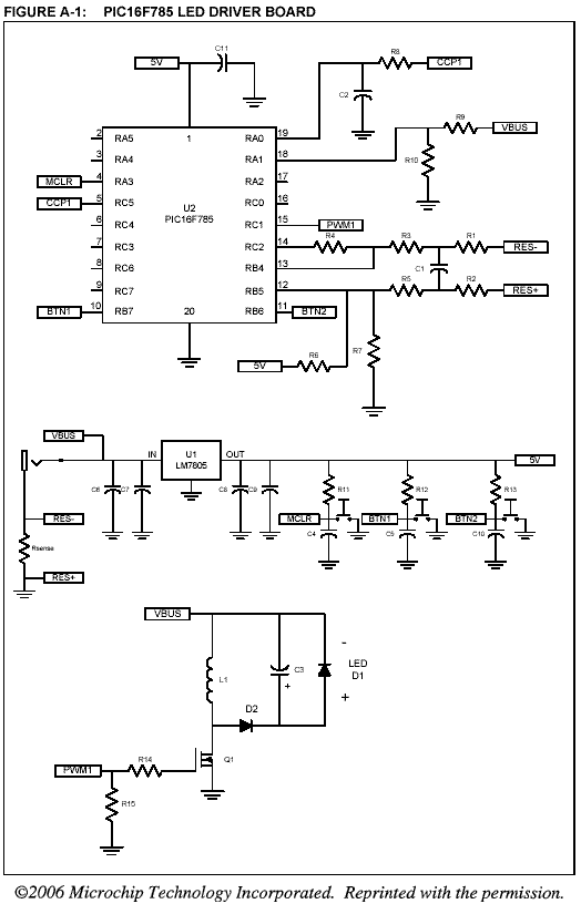
This microcontroller based Project LED Driver uses Microchip Flash based microcontroller PIC16F785 that uses buck boost converter circuit to drive a superbright 5.5W LED module that consumes up to 700mA of current. The LED used in this project is BL-4000 series White 5500K LED Light from Lamina.
The buck boost converter circuit is derived from switching power supply applications which is becoming more common as the overall solution is smaller in size and more efficient compared to linear power supply solutions.
The 20 Pin Flash PIC16F785 is a good device to use as it offers many features some of which are listed below.
- 2048 Words Program Memory, 128 bytes Static RAM, 256 bytes EEPROM.
- Wide Operating Voltage from 2.0V to 5.5V DC.
- 18 I/O.
- 12 channels of 10 bit Analog to Digital Converter.
- 2 operation amplifiers.
- 2 high speed analog comparators and Bandgap voltage reference.
- Capture/Compare/PWM module.
- 2 phase PWM with asynchronous feedback.
- 1 16-bit timer.
- 2 8-bit timers.
The BL-4000 series LED module has a forward voltage drop of approximately 8V for a current limit of 700mA. The on chip operational amplifier is used to amplify the voltage across the resistor that is used to sense the current of the circuit.
This application note from Microchip provides the schematics, source code and some theoretical aspects of buck boost converter for those who are new to switching mode power supplies and its principles of operation.
This project is a good hands-on for electronics designer or hobbyist who are keen to go into the detailed operation of a switching mode power supplies and the latest technology of superbright power LEDs.

Back To Microcontroller Based Project Home Page


New! Comments
Have your say about what you just read! Leave us a comment in the box below.