USB Battery Charger Circuit
USB Battery Charger Circuit
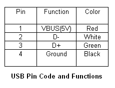
In recent years, the use of USB or Universal Serial Bus as a reliable communications interface in many electronic devices have increased due to its increased speed, size and flexibility. It basically consists of four terminals VBUS(+5V supply), GROUND, D+ and D-.
As many of the gadgets run on rechargeable battery, it is now the trend to design the charging circuit that uses the power supply from the USB port to charge the rechargeable battery. This feature will make the gadgets more convenient to the users as the devices will get their power from the bus and requires no external plug or cables.

USB Bus Powered Functions
There are basically 3 classes of USB functions on power that can be derived from the port.
- Low-Power Bus The low power bus powered functions derived all its power from the VBUS and must not draw more than 1 unit load (100mA) according to the USB standard. It must also be able to work between the VBUS voltage of 4.40V and 5.25V.
- High-Power Bus The high power bus powered functions derived all its power from the VBUS and cannot draw more than 100mA until it has been configured. Once configured, it can draw up to 5 unit loads(500mA) by requesting it in its descriptor. At full load, it must be able to work between the VBUS voltage of 4.75V and 5.25V.
- Self-Power Self power functions can draw up to 100mA from the VBUS and the rest from its external source. This is the most easiest to design.
USB Port Powered Battery Charger
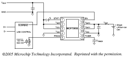
This application circuit uses the MCP73853/MCP73855 linear charge management controllers for cost sensitive applications. They are specially designed for USB applications and adhere to all the USB specifications governing the USB power bus.
The circuit below uses the MCP73855 to design a USB powered Lithium Ion/Lithium Polymer battery charger by deriving the power from the USB port.

USB Battery Charger Circuit Home Page


New! Comments
Have your say about what you just read! Leave us a comment in the box below.