Automotive Battery Charger Project
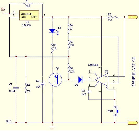
This automotive battery charger project is based on National Semiconductor LM350 3A Adjustable Regulator. It is designed to charge 12V lead acid batteries. When the Switch SW1 is pushed, the output of the charger will go up to 14.5 V. The initial charging current is limited to 2A.
As the charge of the battery continues to rise, the charging current decreases to 150mA and the output voltage is reduced to 12.5V. At this stage, the charging is terminated and the light emitting diode lights up to indicate that charging process is completed.


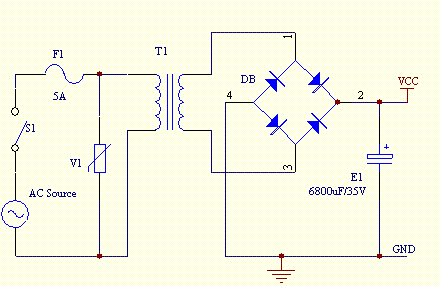
The schematic shows how the various components are connected. The first part of the schematic shows how the DC power supply to LM350 is achieved. The combination use of varistor V1 and Fuse F1 is to protect the circuit from over current and power surge of the mains supply.
Transformer T1 is used to step down the input voltage from mains to 16V AC. Diode bridge DB and electrolytic capacitor E1 are used to rectify the AC voltage to DC voltage.
This rectified DC power supply is fed into the input of the second circuit where LM350 and operational amplifier LM301A are used to control the charging current and voltage of the lead acid battery. Once the charge is full, transistor Q1 will turn ON and LED L1 will be ON to indicate that the charging has been completed. A heat sink is attached to LM350 to transfer the heat generated from the regulator to the ambient.
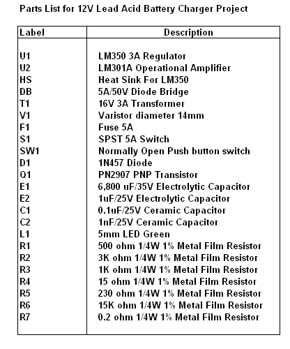
Parts List

Back To Automotive Battery Charger Home Page


New! Comments
Have your say about what you just read! Leave us a comment in the box below.