Temperature Switch Project
This temperature switch project will provide you with an understanding of the use of germanium diode and how it works compared to the more common silicon diode. It works on the principle that as the temperature surrounding the germanium diode increases, the back resistance decreases sharply.
At room temperature, the germanium diode D1 has a typical back resistance of 10K ohm. At this value, the base of transistor Q1 is turned ON, causing transistor Q2 to turn ON as well. When this happens, the base of transistor Q3 is kept to ground causing it to turn OFF hence the buzzer is OFF.
When the temperature of the surrounding increases, the back resistance of the germanium diode D1 decreases sharply causing the base of transistor Q1 to pull down to near ground potential. This cause the transistors Q1 and Q2 to turn OFF. Transistor Q3 is now forward bias through resistor R2 and diode D2. This caused the buzzer to turn ON indicating that the ambient temperature has risen. The sensitivity of the circuit can be adjusted by adjusting variable resistor VR1 and subjecting diode D1 to a temperature that will trigger the buzzer.
Schematic Diagram
The schematic of the project is as shown below. It uses only 10 components to illustrate the understanding of germanium diode and its characteristics. This project is suitable for beginners to electronics and will definitely help to inculcate the interest in designing electronic projects.
You can use any equivalent NPN and PNP transistors to replace BC548 and 2SC2002 respectively as these parts may not be freely available in your country.

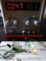
After you have connected all the devices and powered up the circuit, a digital thermometer is required to calibrate the triggering temperature by adjusting the variable resistor VR1. Place the tip of the thermometer close to the germanium diode before when you are calibrating the threshold triggering temperature.

Back To Temperature Switch Project Home Page

Recent Articles
-
Electronics Design Contest
 Join electronics design contest and win prizes. Test your hardware and software skills against the best designers from the rest of the world.
 -
Garden Watering Circuit
 Experiment and test out this automatic garden watering circuit that will detect the moisture of the soil and on or off the water valve accordingly.
 -
Electronics Events
 Join the electronics events to enhance your knowledge and network with other professionals in this industry.
Design and build a battery tester to test dry cell and rechargeable battery with a voltage of less than 2V. Check here.
PCB Prototypes
Make your own printed circuit board and learn the processes involved along the way. More here.
Learn how to dissipate heat from your heat-sensitive electronic components.
Test the reliability of your products to the environment by stressing them in test lab.
Explore the use of 7-Segment Display, 555 Timer, Decade Counter and Binary Adder. Get the circuit.
Construct this simple door bell chime and have fun. Find out more here.
Build this simple home alarm to protect your house from intruders. See the schematic circuit.
New! Comments
Have your say about what you just read! Leave us a comment in the box below.