Digital Temperature Sensor
Have you heard of digital temperature sensor? The use of temperature devices in temperature measurement and sensing have made tremendous progress in the last few decades.There are a few types of measurement solutions that you can implement in your projects. The use of thermistors or thermocouples are the two most widely used devices in measurement solutions.
The recent decade has seen the use of integrated circuits devices in many temperature control related systems because they are much smaller, provide a more accurate measurement and simpler to be integrated to other digital control devices.
Most of the digital temperature sensor system has a built-in communication bus to enable it to communicate with the master control IC. The most used communication interface is called I2C, a simple bi-directional 2-wire bus that was developed by Philips Semiconductors in the 1980's.Since then, many devices has this built in communication protocol that enables all devices that have this feature to be linked together without any other additional components. The I2 interfacing standard has become a world standard that are used in more than 1,000 integrated circuits.
I2C In Brief
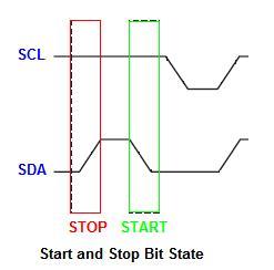
The I2C standard basically define the start, stop, device selection addressing and data transfer interfacing protocol. The hardware consists of 2 I/O lines called SDA and SCL lines. START Condition The Start Data Transfer is initiated when there is a change of state of SDA line from HIGH logic to LOW logic while the SCL line is at HIGH logic. This is the START condition.
STOP Condition
The Stop Data Transfer is initiated when there is a change of state of SDA line from LOW logic to HIGH logic while the SCL line is at HIGH logic. This is the STOP condition.
DATA Transfer Condition
The data transfer is done between the START and STOP conditions with the data being transferred when SCL transition from LOW to HIGH logic. Data is read when SCL is at HIGH logic. SDA line data will only change when SCL line is at LOW logic.
There is no limit to the number of data bytes transferred and is determined by the master device. Acknowledgement of successful transfer of data is done between the master and the slave devices at regular interval.
Digital Temperature Sensor Applications
If you are into designing of thermostat controls for various buildings, industrial controls or home appliances, you may want to consider using the TMP100 digital temperature sensor from Texas Instruments. This device can be connected to the microcontroller using the SCL and SDA lines.
The features of the TMP100 sensor include:
- Low Quiescent standby current of 0.1uA means if you choose a proper microcontroller, the device using battery powered could last for years compared to the use of thermistor.
- Temperature range from -55 °C to 125 °C.
- Wide Power supply range from 2.7V to 5.5V.
- Accuracy of +/- 2.0 °C.
- Resolution up to 0.0625 ° C.
The device is connected to a MCU using a open drain I/O configuration with a pullup resistor of 10K for each of the SCL and SDA lines.
Back To Digital Temperature Sensor Home Page

Recent Articles
-
Electronics Events
Join the electronics events to enhance your knowledge and network with other professionals in this industry. -
Electronics Design Contest
 Join electronics design contest and win prizes. Test your hardware and software skills against the best designers from the rest of the world.
 -
Garden Watering Circuit
 Experiment and test out this automatic garden watering circuit that will detect the moisture of the soil and on or off the water valve accordingly.
Design and build a battery tester to test dry cell and rechargeable battery with a voltage of less than 2V. Check here.
PCB Prototypes
Make your own printed circuit board and learn the processes involved along the way. More here.
Learn how to dissipate heat from your heat-sensitive electronic components.
Test the reliability of your products to the environment by stressing them in test lab.
Explore the use of 7-Segment Display, 555 Timer, Decade Counter and Binary Adder. Get the circuit.
Construct this simple door bell chime and have fun. Find out more here.
Build this simple home alarm to protect your house from intruders. See the schematic circuit.
New! Comments
Have your say about what you just read! Leave us a comment in the box below.