X10 Home Automation Project
Introduction To X10 Home Automation
X-10 is a communication protocol designed for sending signals over 120 VAC wiring. X-10 uses 120 kHz bursts timed with the power line zero-crossings to represent digital information. X10 components send signals through your home electrical wiring.
There are 16 house codes and 16 unit numbers per house code available on your network for a total of 256 addresses. You can control multiple devices by setting them the same house code.
X10 plug in modules are now commonly used in the area of security, lighting, control of TV, motion detectors and other applications. It should be noted if there is no filter at the house breaker box, signals can pass from one house to another and cause odd behavior. If you have problems with a device on a given house and unit code, experiment with other codes and see if the problem goes away.
X-10 transmissions are synchronized with the zero-crossings on the AC power line. By monitoring for the zero-crossings, X-10 devices know when to transmit or receive X-10 information. A binary ‘1’ is represented by a 1 ms long burst of 120 kHz, near the zero-crossing point of the AC. A binary zero is represented by the lack of the 120 kHz burst.
X10 Home Automation Project
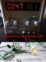
You can get the application note from Microchip that uses PIC16F877A microcontroller for its implementation. It discusses the implementation of X-10 on a PIC micro MCU to create a home controller that can both send and receive X-10 signals. The reader may implement the home controller as it is, or adapt the circuits and firmware to other applications. A library of X-10 functions is provided to facilitate development of other X-10 applications using PIC micro microcontrollers.
It allows the user to program on and off times for up to sixteen devices, using a 2 x 16 liquid crystal display and five push buttons. A built-in light sensor can be used to turn on lights at dusk, and turn them off at The home controller is designed to facilitate experimentation with home automation using the PIC16F877A.
It will be a good project for final year students to embark on and hence gain a considerable experience in X10 wireless technology.
Back To X10 Home Automation Home Page

Recent Articles
-
Electronics Design Contest
 Join electronics design contest and win prizes. Test your hardware and software skills against the best designers from the rest of the world.
 -
Garden Watering Circuit
 Experiment and test out this automatic garden watering circuit that will detect the moisture of the soil and on or off the water valve accordingly.
 -
Electronics Events
 Join the electronics events to enhance your knowledge and network with other professionals in this industry.
Design and build a battery tester to test dry cell and rechargeable battery with a voltage of less than 2V. Check here.
PCB Prototypes
Make your own printed circuit board and learn the processes involved along the way. More here.
Learn how to dissipate heat from your heat-sensitive electronic components.
Test the reliability of your products to the environment by stressing them in test lab.
Explore the use of 7-Segment Display, 555 Timer, Decade Counter and Binary Adder. Get the circuit.
Construct this simple door bell chime and have fun. Find out more here.
Build this simple home alarm to protect your house from intruders. See the schematic circuit.
New! Comments
Have your say about what you just read! Leave us a comment in the box below.