Basics of Thyristors
Introduction To Thyristors
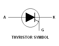
Thyristor is a switching device based on internal regenerative feedback of 2 transistors. One of the most popular type is called silicon controlled rectifier(SCR). They are basically a PNPN structure. They are very reliable and have current ratings up to a few thousands amperes and voltage ratings up to 5000V. The power of this device is that it is able to switch hundreds of watts of load by just supplying a few microwatts pulses onto the Gate of the device.
This device can be turned on in about 1us and turn off in about 15us. This characteristic has enabled it to solve many industrial switching control applications where the switching can go up to a few kHz. It is turned on by making a gate positive with respect to the cathode.
When the gate voltage reaches the threshold voltage and the current reaches the threshold current, the device will turn on and the load current will flow from anode to cathode.
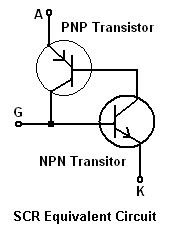
As shown in the figure above, the equivalent circuit of the thyristor consists of 2 transistors, 1 NPN and 1 PNP. By the structure, the Collector of PNP is connected to the base of NPN and hence a Gate is formed. Once the SCR gate is triggered ON, each transistor will hold the other one ON. The characteristic is shown in the figure below.
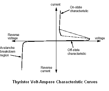
The maximum reverse breakdown voltage must not be exceeded or else the device will be damaged beyond recovery. This device is a unilateral device in that it conduct in one direction only. Once it turned on, the internal resistance will drop to a low value and caused the device to go into saturation.
In AC control circuitry, the device is in series with the load and a gate circuit is used to pulse the gate to turn it on. The turn off of the device is automatic when the AC line passes through zero.
Load power is controlled by the conduction angle of the device. As it is a unilateral device, only half of the waveform can be used. In order to achieve full waveform, 2 devices are used and connected in inverse parallel and a device called triac is formed.
The applications of this device is in the area of motor speed control and in light dimming devices.
Back To Thyristors Home Page

Recent Articles
-
Electronics Events
Join the electronics events to enhance your knowledge and network with other professionals in this industry. -
Electronics Design Contest
 Join electronics design contest and win prizes. Test your hardware and software skills against the best designers from the rest of the world.
 -
Garden Watering Circuit
 Experiment and test out this automatic garden watering circuit that will detect the moisture of the soil and on or off the water valve accordingly.
Design and build a battery tester to test dry cell and rechargeable battery with a voltage of less than 2V. Check here.
PCB Prototypes
Make your own printed circuit board and learn the processes involved along the way. More here.
Learn how to dissipate heat from your heat-sensitive electronic components.
Test the reliability of your products to the environment by stressing them in test lab.
Explore the use of 7-Segment Display, 555 Timer, Decade Counter and Binary Adder. Get the circuit.
Construct this simple door bell chime and have fun. Find out more here.
Build this simple home alarm to protect your house from intruders. See the schematic circuit.
New! Comments
Have your say about what you just read! Leave us a comment in the box below.