Basics of IGBT
IGBT or Insulated Gate Bipolar Transistor is a device that combines the Metal Oxide Semiconductor Field Effect Transistor(MOSFET) gate driving characteristics with the high current and low saturation voltage of bipolar transistor. It acts as a high frequency, high current switch which is used in AC/DC Inverter, motor control and in switching mode power supplies applications.
It has lower VCE(Saturation) voltage which allows it to operate with a higher current density than with bipolar transistor.It can be modeled as a PNP transistor driven by a Power MOSFET. The normal gate driving voltage used is in the region of 15V where saturation voltage is obtained so that conduction losses is kept to a minimum.
The safe operating area is another critical information that shows the maximum operating current and voltage of the device.It shows the forward bias SOA(safe operating area) and reverse bias SOA when the gate emitter junction is forward bias and reversed bias respectively.

The insulated gate bipolar transistor technology is improving with better switching speed, lower conduction voltage drop, higher current carrying capability and higher reliability. The availability of these devices with current up to 1kA, voltage ratings up to 2kV, switching speeds of 200ns and on state voltage down to 2.0V and below have made these devices a popular choice among designers in the world of power electronics.
The advancement of these technology has enabled the inverter system solutions to be implemented for many consumer electronics appliances such as air conditioning controls and refrigerator controls.
Back To IGBT Home Page

Recent Articles
-
Electronics Events
Join the electronics events to enhance your knowledge and network with other professionals in this industry. -
Electronics Design Contest
 Join electronics design contest and win prizes. Test your hardware and software skills against the best designers from the rest of the world.
 -
Garden Watering Circuit
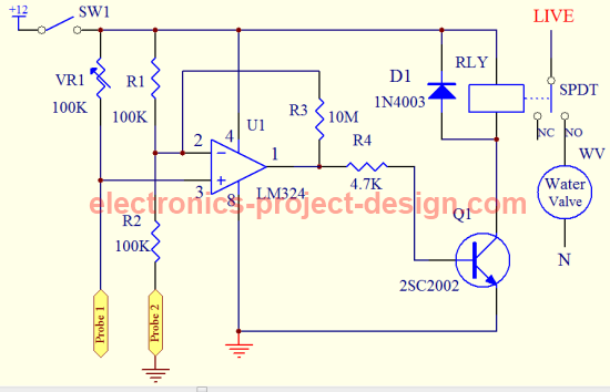 Experiment and test out this automatic garden watering circuit that will detect the moisture of the soil and on or off the water valve accordingly.
Design and build a battery tester to test dry cell and rechargeable battery with a voltage of less than 2V. Check here.
PCB Prototypes
Make your own printed circuit board and learn the processes involved along the way. More here.
Learn how to dissipate heat from your heat-sensitive electronic components.
Test the reliability of your products to the environment by stressing them in test lab.
Explore the use of 7-Segment Display, 555 Timer, Decade Counter and Binary Adder. Get the circuit.
Construct this simple door bell chime and have fun. Find out more here.
Build this simple home alarm to protect your house from intruders. See the schematic circuit.
New! Comments
Have your say about what you just read! Leave us a comment in the box below.