Construct a 9V Door Bell Chime
This door bell chime project provides the schematic and the parts list needed to construct a very simple wired door bell alarm that you can place on the door of your house. It is a very low cost and affordable project that every beginners to electronic design can hands on.
Constructing this project will help the beginners to electronics to understand one of the applications of 555 timer that is configured in an astable mode. This project uses a 555 timer integrated circuit, a speaker, 5 resistors, 4 electrolytic capacitors, 1 ceramic capacitor, 3 diodes, 1 push-button switch and 9 V battery as power supply.
555 Timer Configuration
An astable timer operation is achieved by configuring the circuit in such a way that its output will be triggered continuously. The result of the output is a stream of clock pulses with a fixed pulse width and duty cycle determined by the resistors and capacitor connected to the IC.
In the astable operation, the trigger terminal and the threshold terminal are connected so that a self-trigger is formed, operating as a multivibrator. When the timer output is high, its internal discharging Tr. turns off and the VC1 increases by exponential function with the time constant (RA+RB)*C. When the VC1, or the threshold voltage, reaches 2Vcc/3, the comparator output on the trigger terminal becomes high, resetting the Flip/Flop and causing the timer output to become low. This in turn turns on the discharging Tr. and the C1 discharges through the discharging channel formed by RB and the discharging Tr. When the VC1 falls below Vcc/3, the comparator output on the trigger terminal becomes high and the timer output becomes high again. The discharging Tr. turns off and the VC1 rises again.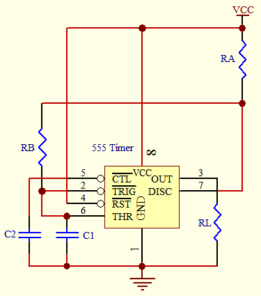
Door Bell Chime Circuit Description

The frequency of the oscillation is given by the formula:
f = 1.44/(RA + 2RB)C where RB= 68K, RA= 68K+39K = 107K , C = 15nF
= 1.44/(175K*15nF)
= 395 Hz
The duty cycle is given by:
DHI = (RA + RB)/(RA + 2RB) = 0.72
DLO = 1 - 0.72 = 0.28
The duration of the pulse is given by:
T1(HIGH) = 0.693(RA+RB)C = 1.82 ms
T2(LOW) = 0.693RB*C = 0.71 ms
Parts List

Back To Door Bell Chime Home Page

Recent Articles
-
Electronics Events
Join the electronics events to enhance your knowledge and network with other professionals in this industry. -
Electronics Design Contest
 Join electronics design contest and win prizes. Test your hardware and software skills against the best designers from the rest of the world.
 -
Garden Watering Circuit
 Experiment and test out this automatic garden watering circuit that will detect the moisture of the soil and on or off the water valve accordingly.
Design and build a battery tester to test dry cell and rechargeable battery with a voltage of less than 2V. Check here.
PCB Prototypes
Make your own printed circuit board and learn the processes involved along the way. More here.
Learn how to dissipate heat from your heat-sensitive electronic components.
Test the reliability of your products to the environment by stressing them in test lab.
Explore the use of 7-Segment Display, 555 Timer, Decade Counter and Binary Adder. Get the circuit.
Construct this simple door bell chime and have fun. Find out more here.
Build this simple home alarm to protect your house from intruders. See the schematic circuit.
New! Comments
Have your say about what you just read! Leave us a comment in the box below.