LED Thermometer
LED Thermometer Circuit Design
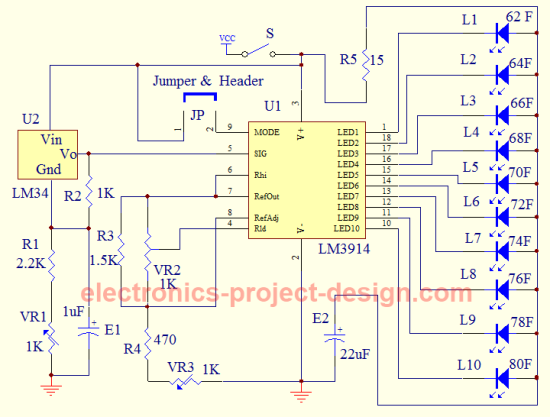
This LED thermometer project uses a standard precision LM34 temperature sensor that has a linear voltage output based on the room temperature in Fahrenheit. If you want to display the temperature in Celcius, you can use the LM35 temperature sensor. There are 3 packages available i.e. TO-92 plastic package, TO-46 metal can package or SO-8 molded package. You can use TO-92 package as it is commonly available in the market.
Circuit
The advantage of LM34 over a thermistor is that the output voltage is linear whereas the thermistor has resistance characteristics that is non-linear. It is also more accurate compared to a thermistor. The only setback is that it is more costly compared to a thermistor.
By calibrating the room temperature to coincide with the output voltage of U1, an accurate room temperature can be displayed on ten light emitting diodes. The LED driver to display the temperature is provided by LM3914. A temperature range of 62 to 80 Fahrenheit will be displayed using the bar mode display setting. In this mode, the jumper JP and its header will need to be installed.
You can use different LED colors to display the room temperature. For instance L1, L2, L3 and L4 can be green. L5, L6, L7 can be orange and L8, L9, L10 red. This will help to differentiate the temperature of the room from afar.
The supply voltage used in this project is 9V DC which is easily available from a typical 9V dry cell battery.
A standard LM34 will provide an output of 10mV/deg Fahrenheit. By using a few resistors, the voltage output can be increased to 40mV/deg Fahrenheit hence giving a wider range of voltage.
Calibration
Power up the circuit by connecting to 9V battery and switching on switch S. Calibrate the LM3914 by using a digital multimeter. Adjust VR3 until pin 6 of LM3914 has a value of 3.385V. After this, do the same for pin 4 until it has a value of 2.505V by adjusting VR2.
Next, place a thermometer near to LM34 in a room that has a temperature range of 62-80 Fahrenheit but not touching it. Adjust VR1 until the correct LEDs light up based on the room temperature measured.
The input voltage at pin 5 of U1 is given by the formula:
Vin = 0.225 + (0.04 X T) where T is the room temperature in Fahrenheit.
Use this formula to check the voltage and the temperature measured.
Parts List
| Label | Description |
| R1 | 2.2K ohm 1% 1/4W Metal Film Resistor |
| R2 | 1K ohm 1% 1/4W Metal Film Resistor |
| R3 | 1.5K ohm 1% 1/4W Metal Film Resistor |
| R4 | 470 ohm 1% 1/4W Metal Film Resistor |
| R5 | 15 ohm 1% 1/4W Metal Film Resistor |
| VR1, VR2, VR3 | 1K ohm Potentiometer |
| S | SPST switch |
| E1 | 1uF/25V Electrolytic Capacitor |
| E2 | 22uF/25V Electrolytic Capacitor |
| U1 IC | LM3914 |
| U2 | LM34 |
| JP | Jumper and Header |
| L1-L10 | Light emitting diodes 5mm or 3mm |
| VCC | 9V Battery and Holder |
More information on LM34 here.
Back to LED Thermometer Home Page

Recent Articles
-
Electronics Events
Join the electronics events to enhance your knowledge and network with other professionals in this industry. -
Electronics Design Contest
 Join electronics design contest and win prizes. Test your hardware and software skills against the best designers from the rest of the world.
 -
Garden Watering Circuit
 Experiment and test out this automatic garden watering circuit that will detect the moisture of the soil and on or off the water valve accordingly.
Design and build a battery tester to test dry cell and rechargeable battery with a voltage of less than 2V. Check here.
PCB Prototypes
Make your own printed circuit board and learn the processes involved along the way. More here.
Learn how to dissipate heat from your heat-sensitive electronic components.
Test the reliability of your products to the environment by stressing them in test lab.
Explore the use of 7-Segment Display, 555 Timer, Decade Counter and Binary Adder. Get the circuit.
Construct this simple door bell chime and have fun. Find out more here.
Build this simple home alarm to protect your house from intruders. See the schematic circuit.
New! Comments
Have your say about what you just read! Leave us a comment in the box below.