Touch Switch Circuit
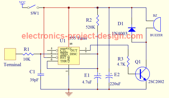
This Touch Switch circuit uses a 555 timer as its core component. The timer operation is configured as a monostable or one shot multivibrator in that once it is triggered, it will output a fixed pulse and remain there for a period which is a function of the time constant t= R2 X E1. In this circuit, the pulse width generated is about 4-4.5 seconds. The trigger is activated by touching the touch terminal.
In this circuit, the output from pin 3 of 555 timer is used to turn ON the NPN transistor Q1. Q1 will in turn activate a buzzer for about 4-4.5 seconds after which it will go OFF. If you need a longer delay, increase the values of R2 and E1. Similarly if a shorter duration is required, reduce the values of R2 and E1.
The Vcc used is 9V from a battery. For safety reason, it is important that you do not use any power supply from mains unless the power supply is designed with isolating transformer that comforms to the safety standard such as UL. Improperly designed power supply may cause shock to you when you touch the terminal hence it is always better to use a dry cell battery for this project.
Besides the buzzer, you can modify the circuit to on a series of light emitting diodes once the terminal is touched.
Touch Switch Parts List
| Label | Description |
| R1 | 10K ohm 1% 1/4W Metal Film Resistor |
| R2 | 520K ohm 1% 1/4W Metal Film Resistor |
| R3 | 4.7K ohm 1% 1/4W Metal Film Resistor |
| C1 | 39pF/25V Ceramic Capacitor |
| E1 | 4.7uF/25V Electrolytic Capacitor |
| E2 | 220uF/25V Electrolytic Capacitor |
| SW1 | SPST switch |
| Q1 | 2SC2002 NPN Transistor |
| BZ | 9V Buzzer |
| U1 | 555 Timer |
| D1 | Diode 1N4003 |
| Terminal | Touch Terminal |
Back To Touch Switch Circuit Home Page

Recent Articles
-
Electronics Events
Join the electronics events to enhance your knowledge and network with other professionals in this industry. -
Electronics Design Contest
 Join electronics design contest and win prizes. Test your hardware and software skills against the best designers from the rest of the world.
 -
Garden Watering Circuit
 Experiment and test out this automatic garden watering circuit that will detect the moisture of the soil and on or off the water valve accordingly.
Design and build a battery tester to test dry cell and rechargeable battery with a voltage of less than 2V. Check here.
PCB Prototypes
Make your own printed circuit board and learn the processes involved along the way. More here.
Learn how to dissipate heat from your heat-sensitive electronic components.
Test the reliability of your products to the environment by stressing them in test lab.
Explore the use of 7-Segment Display, 555 Timer, Decade Counter and Binary Adder. Get the circuit.
Construct this simple door bell chime and have fun. Find out more here.
Build this simple home alarm to protect your house from intruders. See the schematic circuit.
New! Comments
Have your say about what you just read! Leave us a comment in the box below.