LED Circuit To Assist You In The Dark
This LED Circuit that uses two high intensity light emitting diodes, a transistor, an electrolytic capacitor, a normally open push button switch, a 9V battery, battery holder and two resistors. It is one of the simplest electronics project that you can embark on. When the button is pressed and released, the LEDs will light up for about 15-20 seconds before it automatically goes OFF.
This project is useful when you need a small focused light to help you find something in the dark or simply to light up a pathway for a couple of seconds. As no sensor is involved, the cost of constructing this circuit is low and the components used can be purchased from any electronics shop. The values of the components are not too critical hence you can use a substitute part if the exact part is not available.
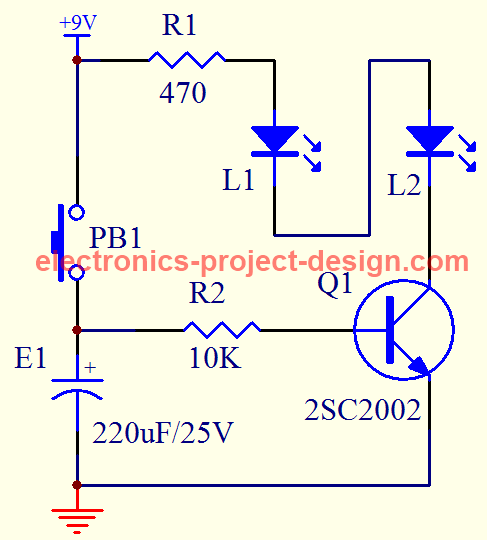
In the LED circuit shown, when the switch PB1 is pressed and released, the power supply 9V from the battery will cause a positive bias voltage between the base and emitter of transistor Q1. As a result, the transistor will turn ON and light emitting diodes L1 and L2 will turn ON.
The resistor R2 is used to limit the current into the base of the transistor to 0.83 mA. The value of resistor R2 can be changed but ensure that the current flowing through the base of Q1 is between 1mA to 5mA.
At the same time PB1 is pressed, electrolytic capacitor E1 is charged to a level slightly lower than 9V. As the switch is released, the charge at E1 will continue to provide a positive bias voltage to the base of Q1, keeping it ON.
The charge will continue to be discharged through the PN junction of Q1. After about 15-20 seconds of discharge, the voltage at E1 will drop to below 0.7V causing the transistor to turn OFF. The LEDs will also turn OFF.
Make sure you use high intensity light emitting diodes that can give at least 2,000 milicandelas. Normal LED will only give 20-50 milicandelas and is not suitable to illumine a space.
Resistor R1 value is set at 470 ohm and is used to limit the current flowing though the LEDs. You can experiment with different value of R1 and see the light intensity changing. Use a lower R1 if you need a higher intensity and a higher R1 if you need a lower intensity. The battery life will be shorter if you set a higher intensity hence strike a balance between the power consumption and illumination needed.
Further power saving can be obtained by using only one LED instead of two.
LED Circuit Parts List
| Label | Description |
| R1 | 470 ohm 5% Carbon Film Resistor 1/4W |
| R2 | 10K ohm 5% Carbon Film Resistor 1/4W |
| E1 | 220uF/25V Electrolytic Capacitor |
| L1, L2 | Ultra bright high intensity LED |
| PB1 | NO Push Button Switch |
| Q1 | NPN Transistor 2SC2002 |
| Bat & Holder | 9V Alkaline Battery and Holder |

Recent Articles
-
Electronics Design Contest
 Join electronics design contest and win prizes. Test your hardware and software skills against the best designers from the rest of the world.
 -
Garden Watering Circuit
 Experiment and test out this automatic garden watering circuit that will detect the moisture of the soil and on or off the water valve accordingly.
 -
Electronics Events
 Join the electronics events to enhance your knowledge and network with other professionals in this industry.
Design and build a battery tester to test dry cell and rechargeable battery with a voltage of less than 2V. Check here.
PCB Prototypes
Make your own printed circuit board and learn the processes involved along the way. More here.
Learn how to dissipate heat from your heat-sensitive electronic components.
Test the reliability of your products to the environment by stressing them in test lab.
Explore the use of 7-Segment Display, 555 Timer, Decade Counter and Binary Adder. Get the circuit.
Construct this simple door bell chime and have fun. Find out more here.
Build this simple home alarm to protect your house from intruders. See the schematic circuit.
New! Comments
Have your say about what you just read! Leave us a comment in the box below.