Electronic Time Clock
This electronic time clock application note uses an 18 pin PIC16C54 microcontroller as its core in the display and settings of a simple 4 digits electronic clock. The four 7 segment displays are connected in a multiplexing method and each segment is sequentially by controlling the Common Cathode of each 7 segment.
The common cathodes are connected to 4 pins of PORTA of the microcontroller. When the pin in PORTA is LOW, the transistor connected to it will turn ON and that particular 7 segment is turn ON. PortB will activate the segments of that particular 7 segment that has been chosen.
By multiplexing the selection of the 7 segment sequentially, an equal brightness of all the 7 segments display will be achieved.
Multiplexing has the advantage in that it helps to reduce the number of ports needed to connect to the 7 segments. It also keep the cost of a device low as fewer parts are needed. The setback is that the display may not be as bright as if it is driven directly without multiplexing.
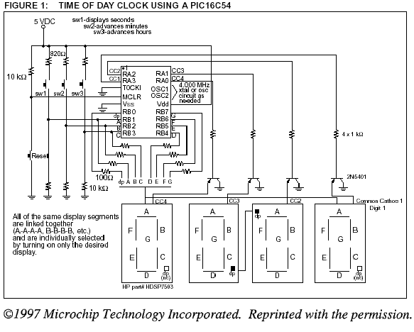
The 3 switches are also connected to PORTB. They are pulled down to logic "0" by using a 10k ohm resistors. Inputs of the switches are detected as logic "1" by the MCU by connecting a pull up resistor to the VDD. Pressing SW1 changes the seconds setting, SW2 the minutes setting and SW3 the hour setting.
Electronic Time Clock Home Page

Recent Articles
-
Electronics Design Contest
 Join electronics design contest and win prizes. Test your hardware and software skills against the best designers from the rest of the world.
 -
Garden Watering Circuit
 Experiment and test out this automatic garden watering circuit that will detect the moisture of the soil and on or off the water valve accordingly.
 -
Electronics Events
 Join the electronics events to enhance your knowledge and network with other professionals in this industry.
Design and build a battery tester to test dry cell and rechargeable battery with a voltage of less than 2V. Check here.
PCB Prototypes
Make your own printed circuit board and learn the processes involved along the way. More here.
Learn how to dissipate heat from your heat-sensitive electronic components.
Test the reliability of your products to the environment by stressing them in test lab.
Explore the use of 7-Segment Display, 555 Timer, Decade Counter and Binary Adder. Get the circuit.
Construct this simple door bell chime and have fun. Find out more here.
Build this simple home alarm to protect your house from intruders. See the schematic circuit.
New! Comments
Have your say about what you just read! Leave us a comment in the box below.