Analog Delay Timer
In this Delay Timer project, all analog parts are being used with the thyristor as a device that switches an AC Relay ON or OFF depending on the timing of the RC circuit. The input mains supply used ranges from 220VAC to 240VAC and an AC relay (220-240VAC) is used to switch a load. The load to be switched must be within the current and relay ratings.
This circuit is useful for use of devices that need to be OFF for a minimum of 150 - 210 secs after a mains supply have cuts off. Devices such as compressors and halogen lamp cannot be OFF and ON repeatedly within a short period of time as it will cause damage to the devices.
The use of microcontroller based devices are not reliable in that if the power supply cuts off and came back again in a short period of time, it will reset and "forgotten" its previous state. The use of RC circuitry as a timer circuit is reliable and is not susceptible to "memory loss" as in the case of microcontroller.
If a microcontroller based solution is used, extra circuitry such as backup battery or supercapacitor need to be incorporated in order to retain the memory of the MCU and to ensure that the clock still runs even after the supply has cuts off.
This project should be handled by experienced electronics designer as its part are powered on directly from the mains supply.
As all parts is "live", one may get electric shock if care is not taken when testing the circuit. Some parts may "burst" if there are some short circuit in the circuit. It is not recommended to use breadboard to test the circuit. Circuit should be tested using printed circuit board and an isolating variable transformer where the voltage is slowly ramped up from zero.
Once tested working, the components should be potted using epoxy with only the terminals exposed. All parts are potted to prevent users from touching the parts.
Schematic Diagram
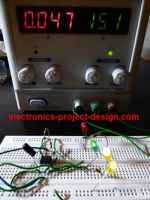
The schematic below shows the circuit diagram of the ON delay timer. Once the mains power supply cuts off, the relay will only be able to turn ON after a period of 150 - 210 secs depending on the tolerance of the RC circuit represented by resistor R7(5.1 Mohm) and electrolytic capacitor E2(47uF). More accurate timing can be achieved by using low tolerance resistor and capacitor.
The thyristor used can be either 2P6M or MCR106-8 or equivalent parts available in the market. Relays used should have coil ratings below 1A in order not to overheat the SCR. No heatsink is required for the SCR.
At power on, there is no charge at E2, hence the transistor Q2 will be forward bias and turn ON when Q3 turn ON. Once these two transitors are ON, the SCR will turn ON as well. The use of C1 and R6 across the SCR acts as a snubber circuit to reduce the switching noise generated by the SCR when it turns OFF/ON. During the ON stage of the SCR, the capacitor E2 is charged to its maximum value.
When the mains supply cuts off, the charge at capacitor E2 will cause the base of transistor Q2 to be reverse bias and cannot turn ON until almost all the charges have been discharged through resistor R7. Once the charge has been discharged (which will take around 150 - 210 secs for the values shown), transistor Q2 will be able to turn ON.
The timing of the circuit can be changed by reducing or increasing the RC values of R7 and E2.

Parts List


Recent Articles
-
Electronics Design Contest
 Join electronics design contest and win prizes. Test your hardware and software skills against the best designers from the rest of the world.
 -
Garden Watering Circuit
 Experiment and test out this automatic garden watering circuit that will detect the moisture of the soil and on or off the water valve accordingly.
 -
Electronics Events
 Join the electronics events to enhance your knowledge and network with other professionals in this industry.
Design and build a battery tester to test dry cell and rechargeable battery with a voltage of less than 2V. Check here.
PCB Prototypes
Make your own printed circuit board and learn the processes involved along the way. More here.
Learn how to dissipate heat from your heat-sensitive electronic components.
Test the reliability of your products to the environment by stressing them in test lab.
Explore the use of 7-Segment Display, 555 Timer, Decade Counter and Binary Adder. Get the circuit.
Construct this simple door bell chime and have fun. Find out more here.
Build this simple home alarm to protect your house from intruders. See the schematic circuit.
New! Comments
Have your say about what you just read! Leave us a comment in the box below.