Basic Electronic Project - 555 Timer
This basic electronic project is configured as a Schmitt trigger that switches on a lamp when the environment turns dark. The popular 555 timer which has been around for decades is used together with a light dependent resistor to make it happen.
Schmitt Trigger
A Schmitt trigger is basically a comparator that is used to ensure that rapid changes in the input voltage due to a fluctuation in sensor does not caused the output to change unless a threshold input has been reached.
In this circuit, it is used to prevent the output voltage to swing ON or OFF causing chattering. Chattering will cause the life cycle of the relay to be greatly reduce and the lamp will turn on and off repeatedly.
Fine tune the sensitivity of the circuit by varying the potentiometer VR1 until you are satisfied with the performance of the circuit.
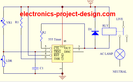
The hysteresis is created by connecting resistor R2 to the output pin 3 of the 555 Timer. LDR is made of Cadmium Sulfide that has resistance inversely propotional to the amount of light shining on it.
In bright environment, the LDR will register a resistor value of 1k and below causing the voltage at input pin 2 to be low. This in turn caused the output at pin 3 to be high, turning OFF the relay. The lamp will not light up. Use a DC power supply voltage of 12V and a DC 12V relay.
When the environment is dark, the LDR resistance will go very high up to 1 Mega ohm. In this case, the voltage at pin 2 will be high causing the relay to be turned ON. This will ON the lamp. This circuit is useful when you need to automatically light up a place when it is dark.
Test the circuit by using a bright light to shine on the LDR. The lamp should turn OFF. Turn off the light and ensure the environment is dark. The lamp should turn ON. Test it with different light intensity and adjust VR1 accordingly.
Basic Electronic Project Parts List
| Label | Description |
| R1 | 22K ohm 5% 1/4W Carbon Film Resistor |
| R2 | 300K ohm 5% 1/4W Carbon Film Resistor |
| VR1 | 10K ohm Potentiometer |
| LDR | Light Dependent Resistor |
| C1 | 0.01uF/25V Ceramic Capacitor |
| D1 | 1N4003 Diode |
| 555 Timer | 555 Timer IC |
| L1 | AC LAMP |
Try experimenting the circuit by changing the resistors R1 and R2. You can also change the circuit to make it sensitive to high temperature by using a thermistor instead of LDR.
Instead of turning on the lamp, a buzzer that generates an audible sound continuously can also be used. However, take care of the power supply to the buzzer. Most buzzer is DC operated. If the buzzer is 12V operated, a direct connection from the 12 V DC supply is connected to one end of the buzzer and the other end to pin 3 of the timer.
Back To Basic Electronic Project 555 Timer Home Page

Recent Articles
-
Electronics Design Contest
 Join electronics design contest and win prizes. Test your hardware and software skills against the best designers from the rest of the world.
 -
Garden Watering Circuit
 Experiment and test out this automatic garden watering circuit that will detect the moisture of the soil and on or off the water valve accordingly.
 -
Electronics Events
 Join the electronics events to enhance your knowledge and network with other professionals in this industry.
Design and build a battery tester to test dry cell and rechargeable battery with a voltage of less than 2V. Check here.
PCB Prototypes
Make your own printed circuit board and learn the processes involved along the way. More here.
Learn how to dissipate heat from your heat-sensitive electronic components.
Test the reliability of your products to the environment by stressing them in test lab.
Explore the use of 7-Segment Display, 555 Timer, Decade Counter and Binary Adder. Get the circuit.
Construct this simple door bell chime and have fun. Find out more here.
Build this simple home alarm to protect your house from intruders. See the schematic circuit.
New! Comments
Have your say about what you just read! Leave us a comment in the box below.